(New page: Category:ECE637 Category:sLecture Category:image processing Category:lecture notes sLecture :↳ [[ECE637_to...) |
|||
| Line 39: | Line 39: | ||
---- | ---- | ||
| + | ==Integration Along Projections== | ||
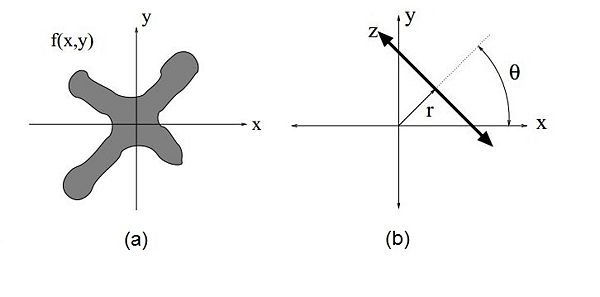
| + | Consider the function f(x,y) shown in figure 1(a). You can think of <math>f(x,y)</math> as the original image. <math>f(x,y)</math> is some grey-scale image where brighter pixels correspond to higher densities (like classical X-rays). | ||
| + | [[Image:RT_fig1_mh.jpeg|600px|thumb|left|Fig 1: Orientation of <math>r,z</math> axes relative to <math>x,y</math> axes]] | ||
| + | |||
| + | |||
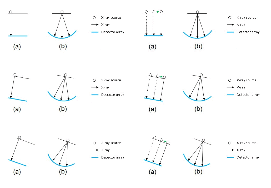
| + | We measure the projections as an integral of <math>f</math> along the <math>z</math> axis for every <math>r</math>. The orientation of the <math>r,z</math> coordinate axes relative to the <math>x,y</math> axes is shown in figure 1(b). The <math>z</math> axis is parallel to the direction of X-rays. For this analysis, we assume, for the sake of simplicity, that the source and detectors employ parallel beam geometry. The path traced by the source is shown in figure 2(a). This design is obsolete now. As we discussed earlier, scanners nowadays employ fan beam geometry shown in figure 2(b). | ||
| + | |||
| + | [[Image:RT_fig2_mh.gif|600px|thumb|left|Fig 2: (a) The source translates to trace out a straight line of sources before the source-detector combo rotate to a different angle. (b) Newer fan beam technology. Wavefronts resemble a spherical surface.]] | ||
| + | |||
| + | |||
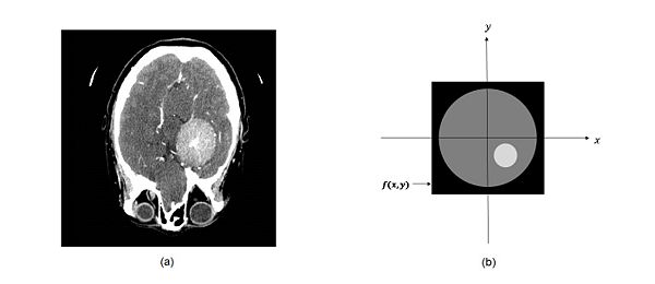
| + | Let's take a look at another example. Figure 3(a) shows a CT slice through a subject's brain. Let us simplify that image to the one shown in figure 3(b) for the sake of illustration. What would its projection look like? | ||
| + | |||
| + | [[Image:RT_fig3_mh.jpeg|600px|thumb|left|Fig 3: (a) A CT slice through a brain. (b) A simplified version of the image in (a).]] | ||
| + | |||
| + | |||
| + | [[Image:RT_fig4_mh.jpeg|600px|thumb|left|Fig 4: Projection of <math>f(x,y)</math> for the given <math>\theta</math> and <math>z</math>]] | ||
| + | |||
| + | |||
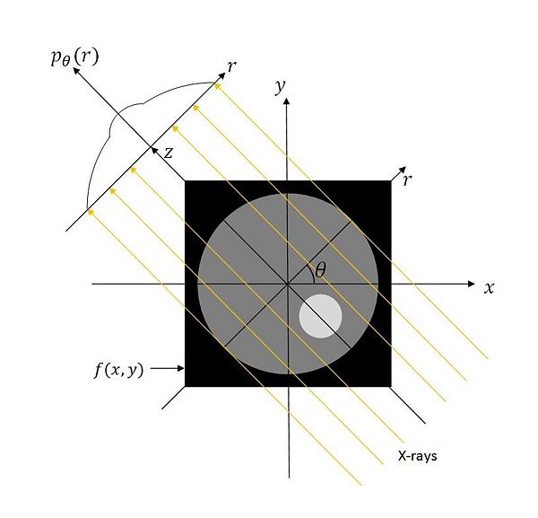
| + | For a given <math>\theta</math>, the X-rays are <math>\theta</math> degrees counterclockwise from the <math>y</math> axis. The line integral along <math>z</math> is measured for every <math>r</math> at the given <math>\theta</math>. Notice the sudden humps that appear in the graph of <math>p_{\theta}(r)</math> as we cross into brighter territories. This is because there are pixels with higher values on the <math>z-</math>axis for certain <math>r</math> values. | ||
| + | |||
| + | Since the image is only available to us as a function of <math>x</math> and <math>y</math>, we must first rotate the <math>(x,y)</math> coordinates to express them in terms of <math>r</math> and <math>z</math>. This coordinate rotation was covered in the [[ECE637_tomographic_reconstruction_coordinate_rotation_S13_mhossain|last section]]. | ||
| + | |||
| + | The projection integral for each <math>r</math> and <math>\theta</math> is given by <br/> | ||
| + | <math>\begin{align} | ||
| + | p_{\theta}(r) &= \int_{-\infty}^{\infty}f(A_{\theta} | ||
| + | \begin{bmatrix} | ||
| + | r \\ | ||
| + | z | ||
| + | \end{bmatrix}) dz \\ | ||
| + | &= \int_{-\infty}^{\infty} f(r\cos(\theta)-z\sin(\theta),r\sin(\theta)+z\cos(\theta))dz | ||
| + | \end{align}</math> | ||
| + | |||
| + | |||
| + | ---- | ||
| + | |||
| + | ==Definition == | ||
| + | |||
| + | We have just derived the Radon transform of the function f(x,y). So we have that <br/> | ||
| + | <math>p_{\theta}(r)= \int_{-\infty}^{\infty} f(r\cos(\theta)-z\sin(\theta),r\sin(\theta)+z\cos(\theta))dz</math><br/> | ||
| + | where <math>p_{\theta}</math> is the Radon transform of <math>f(x,y)</math>. | ||
| + | |||
| + | Once again, the Geometric interpretation is shown in figure 5. | ||
| + | |||
| + | [[Image:RT_fig5_mh.jpeg|400px|thumb|left|Fig 5: Geometric interpretation shown in Professor Bouman's notes]] | ||
| + | |||
| + | |||
| + | Notice that the projection corresponding to <math>r = 0</math> goes through the point <math>(x,y) = (0,0)</math>. | ||
Revision as of 14:00, 25 May 2013
- ↳ Topic 2: Tomographic Reconstruction
- ↳ Intro
- ↳ CT
- ↳ PET
- ↳ Co-ordinate Rotation
- ↳ Radon Transform
The Bouman Lectures on Image Processing
A sLecture by Maliha Hossain
Subtopic 3: Radon Transform
© 2013
Contents
Excerpt from Prof. Bouman's Lecture
Accompanying Lecture Notes
Integration Along Projections
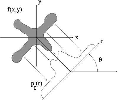
Consider the function f(x,y) shown in figure 1(a). You can think of $ f(x,y) $ as the original image. $ f(x,y) $ is some grey-scale image where brighter pixels correspond to higher densities (like classical X-rays).
We measure the projections as an integral of $ f $ along the $ z $ axis for every $ r $. The orientation of the $ r,z $ coordinate axes relative to the $ x,y $ axes is shown in figure 1(b). The $ z $ axis is parallel to the direction of X-rays. For this analysis, we assume, for the sake of simplicity, that the source and detectors employ parallel beam geometry. The path traced by the source is shown in figure 2(a). This design is obsolete now. As we discussed earlier, scanners nowadays employ fan beam geometry shown in figure 2(b).
Let's take a look at another example. Figure 3(a) shows a CT slice through a subject's brain. Let us simplify that image to the one shown in figure 3(b) for the sake of illustration. What would its projection look like?
For a given $ \theta $, the X-rays are $ \theta $ degrees counterclockwise from the $ y $ axis. The line integral along $ z $ is measured for every $ r $ at the given $ \theta $. Notice the sudden humps that appear in the graph of $ p_{\theta}(r) $ as we cross into brighter territories. This is because there are pixels with higher values on the $ z- $axis for certain $ r $ values.
Since the image is only available to us as a function of $ x $ and $ y $, we must first rotate the $ (x,y) $ coordinates to express them in terms of $ r $ and $ z $. This coordinate rotation was covered in the last section.
The projection integral for each $ r $ and $ \theta $ is given by
$ \begin{align} p_{\theta}(r) &= \int_{-\infty}^{\infty}f(A_{\theta} \begin{bmatrix} r \\ z \end{bmatrix}) dz \\ &= \int_{-\infty}^{\infty} f(r\cos(\theta)-z\sin(\theta),r\sin(\theta)+z\cos(\theta))dz \end{align} $
Definition
We have just derived the Radon transform of the function f(x,y). So we have that
$ p_{\theta}(r)= \int_{-\infty}^{\infty} f(r\cos(\theta)-z\sin(\theta),r\sin(\theta)+z\cos(\theta))dz $
where $ p_{\theta} $ is the Radon transform of $ f(x,y) $.
Once again, the Geometric interpretation is shown in figure 5.
Notice that the projection corresponding to $ r = 0 $ goes through the point $ (x,y) = (0,0) $.
References
- C. A. Bouman. ECE 637. Class Lecture. Digital Image Processing I. Faculty of Electrical Engineering, Purdue University. Spring 2013.
Questions and comments
If you have any questions, comments, etc. please post them on this page
Back to the "Bouman Lectures on Image Processing" by Maliha Hossain

