- ↳ Topic 2: Tomographic Reconstruction
- ↳ Intro
- ↳ CT
- ↳ PET
- ↳ Co-ordinate Rotation
- ↳ Radon Transform
- ↳ Fourier Slice Theorem
- ↳ Convolution Back Projection
The Bouman Lectures on Image Processing
A Slecture by Maliha Hossain
Subtopic 1: Intro to Tomographic Reconstruction
© 2013
Contents
[hide]Excerpt from Prof. Bouman's Lecture
Introduction to Tomography
An Overview of the Reconstruction Process
Accompanying Lecture Notes
Tomography refers to the method of producing images of plane sections, or slices of a solid object. The word is derived from Greek tomos meaning section.
At this point let me introduce a few common medical imaging modalities:
- Anatomical Imaging Modalities
- Chest X-ray
- Computed Tomography (CT)
- Magnetic Resonance Imaging (MRI)
- Functional Imaging Modalities
- Signal Photon Emission Tomography (SPECT)
- Positron Emission Tomography (PET)
- Functional Magnetic Resonance Imaging (fMRI)
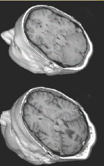
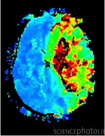
Anatomical imaging modalities only reveal the structure of an object, Figure 1, for example, compares MRI scans of two patients. Functional imaging modalities can differentiate between active and inactive cells. So they can sort of tell you what the tissue is doing at a given time. Figure 2 shows an fMRI scan of a woman's brain after a stroke. The scan measures the oxygen concentration of the brain cells. Active neurons have higher concentrations.
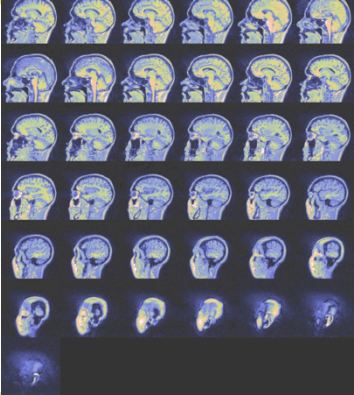
It is important to realize that CT, PET and MRI are three-dimensional imaging modalities and must be visualized in voxels. Figure 3 illustrates how an MRI scan produces multiple slices to build up a representation of a three-dimensional volume. Compare this to the classical chest X-ray, which is a two-dimensional scan and built up of pixels. When you look at a planar chest X-ray, you see the image of the heart, the lungs, the rib cage and the vertebrae superimposed on one another. This makes accurate diagnosis difficult.
We can use the CSFT to analyze applications such as tomography and MRI imaging without getting into sampling and discrete time systems. Of course in reality, these scans are performed by computers and must be implemented digitally but for now the CSFT will suffice in building an understanding of these systems.
While the measurements from MRI and tomography can both be analyzed by CSFT, both the physics and the mathematics behind the two cases are completely different as they are governed by very different sets of equations that represent two very distinct techniques.
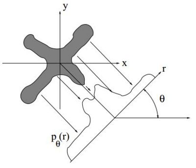
CT and PET are two examples of modalities that use tomography to reconstruct an a three-dimensional representation of an object. While the physics of these two modalities are very different, we will see that for both cases, we measure the line integral of the density through the material. So if you get the projection through the object at each point, at an angle $ \theta $, you get the one-dimensional function of the projections. Once you have made the measurement form every angle, you can reconstruct the object. It's as if you are looking at an object and you cannot see around it because the object blocks your view but if you tilt your head to different angles, you can see the back of the object. So that is the intuition behind tomography, that by looking at different angles, you can obtain different views and form a consistent interpretation of all the views. If you have only a single view, there is information you have lost. But if you have lots of different views, you can put them all together to get a three-dimensional interpretation of the object. Compare this to how both your eyes work together in binocular vision to give you a perception of depth. You have two points of view and your brain processes the two separate images to allow you to perceive your surroundings in three dimensions.
Let $ f(x,y) $ be the the density of the object to be scanned as a function of spatial co-ordinates $ x $ and $ y $.
Let $ p_{\theta}(r) $ be the forward projections collected at angle $ \theta $. The forward projections are known as Radon Transforms. Projections must be collected at every angle $ \theta $ and displacement $ r $.
So your scanner measures the $ p_{\theta}(r) $ at every $ \theta $ and $ r $. Once you have collected your data, i.e the projections, you would want to form a three-dimensional representation of the object. Tomographic reconstruction is an example of an inversion process where your measurements are the linear transform of your object and you are essentially trying to invert this linear transform. The Fourier Slice Theorem is the basis of this inversion. It provides the theory to solve the problem but it does not tell you how to get the problem solved on a computer. There are many ways of using the theorem to get the answer but a practical and commonly used method is to use convolution back projection (CPB) to perform the computation.
The Fourier Slice Theorem and CPB will be covered in more detail in the following sections of this topic along with an overview of how CT and PET scanners are designed.
References
- C. A. Bouman. ECE 637. Class Lecture. Digital Image Processing I. Faculty of Electrical Engineering, Purdue University. Spring 2013.
- G. Francis. Psy 200. "Introduction to Cognitive Psychology". Class Lecture Notes. Faculty of Psychological Sciences, Purdue University. Spring 2013.
Questions and comments
If you have any questions, comments, etc. please post them on this page
Back to the "Bouman Lectures on Image Processing" by Maliha Hossain

