| (3 intermediate revisions by 2 users not shown) | |||
| Line 1: | Line 1: | ||
| + | = Thévenin's theorem = | ||
| + | by ECET undergraduate student [[user:Jflick|Justin Flick]]. | ||
| + | ---- | ||
| + | The application of Thévenin's theorem enables multiple voltage and/or current sources and resistors to be represented by a single voltge source and resistor. This greatly simplifies analysis and troubleshooting a circuit when changes are made in areas other than the power supply. | ||
| + | <br> | ||
| − | + | One set of rules to 'Thévenize' a circuit is as follows. | |
| + | *Find the unloaded voltage output of the source using voltage divider rules. | ||
| + | *Find the total resistance of the circuit across the nodes 'connected to the outside'. This can be done by replacing all voltage sources with a short all current sources with an open circuit. | ||
| + | <br> | ||
| − | + | == Example: == | |
| + | ---- | ||
| + | A 15Vdc source is connected to a 4 resistor series parallel circuit with output nodes A and B. | ||
| + | [[Image:Thevenin 001.PNG]] | ||
| + | Step 1. Use voltage divider rules to find the unloaded voltage at the output. | ||
| + | <math>V_{out}=15V*\frac{5k\Omega}{(2k\Omega+3k\Omega)}=7.5V</math> | ||
| − | [[ | + | <math>R_{total} = 8k\Omega + \frac{1}{(2k\Omega+3k\Omega)^{-1}+ 5k\Omega^{-1}} = 10.5k\Omega</math> |
| + | |||
| + | <br> | ||
| + | |||
| + | == Verification: == | ||
| + | Testing a Thevenin power supply under load should reveal that it is equivilent to the original. placing a 13kohm load in parallel with the output will load both circuits similarly. | ||
| + | [[Image:Thevenin 002.PNG]] | ||
| + | |||
| + | <math>15V_{Ein}-\frac{15V_{Ein}*5k\Omega_{load}}{((2k\Omega_{R3}+3k\Omega_{R4})^{-1}+(8k\Omega_{R2}+13k\Omega_{Rload})^{-1})^{-1}+5) }*\frac{13k\Omega_{R1}}{(8k\Omega_{R2}+13k\Omega_{Rload})}=4.148V</math> | ||
| + | |||
| + | <math>7.5V*\frac{13k\Omega}{(10.5k\Omega+13k\Omega)}=4.148V</math> | ||
| + | ---- | ||
| + | [[2009_Fall_ECET_107_Fahlsing|Back to ECET107Fall2009Fahlsing]] | ||
Latest revision as of 08:51, 9 December 2010
Thévenin's theorem
by ECET undergraduate student Justin Flick.
The application of Thévenin's theorem enables multiple voltage and/or current sources and resistors to be represented by a single voltge source and resistor. This greatly simplifies analysis and troubleshooting a circuit when changes are made in areas other than the power supply.
One set of rules to 'Thévenize' a circuit is as follows.
- Find the unloaded voltage output of the source using voltage divider rules.
- Find the total resistance of the circuit across the nodes 'connected to the outside'. This can be done by replacing all voltage sources with a short all current sources with an open circuit.
Example:
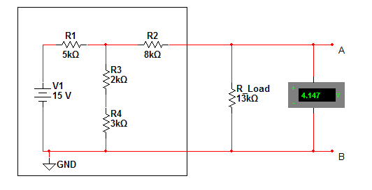
A 15Vdc source is connected to a 4 resistor series parallel circuit with output nodes A and B.
Step 1. Use voltage divider rules to find the unloaded voltage at the output.
$ V_{out}=15V*\frac{5k\Omega}{(2k\Omega+3k\Omega)}=7.5V $
$ R_{total} = 8k\Omega + \frac{1}{(2k\Omega+3k\Omega)^{-1}+ 5k\Omega^{-1}} = 10.5k\Omega $
Verification:
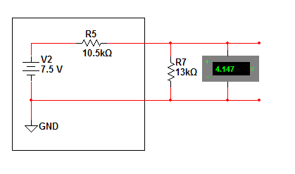
Testing a Thevenin power supply under load should reveal that it is equivilent to the original. placing a 13kohm load in parallel with the output will load both circuits similarly.

$ 15V_{Ein}-\frac{15V_{Ein}*5k\Omega_{load}}{((2k\Omega_{R3}+3k\Omega_{R4})^{-1}+(8k\Omega_{R2}+13k\Omega_{Rload})^{-1})^{-1}+5) }*\frac{13k\Omega_{R1}}{(8k\Omega_{R2}+13k\Omega_{Rload})}=4.148V $
$ 7.5V*\frac{13k\Omega}{(10.5k\Omega+13k\Omega)}=4.148V $


