| Line 51: | Line 51: | ||
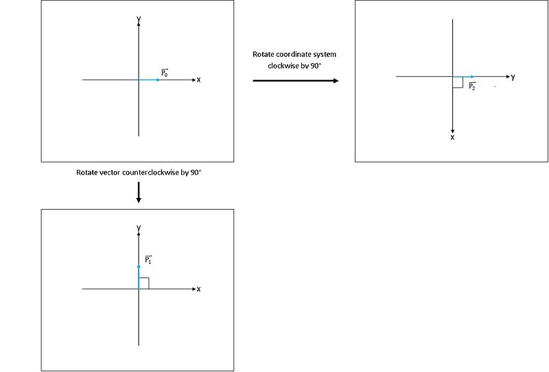
[[Image:CR_fig1_mh.jpeg|800px|thumb|left|Fig 1: bottom left: ccw rotation of vector; top right: cw rotation of coordinate axes]] | [[Image:CR_fig1_mh.jpeg|800px|thumb|left|Fig 1: bottom left: ccw rotation of vector; top right: cw rotation of coordinate axes]] | ||
| − | + | Let <math>{P_0}</math> be the unit vector shown in the top left corner of figure 1. <br/> | |
| + | <math>P_0 = \begin{bmatrix} | ||
| + | 1 \\ | ||
| + | 0 | ||
| + | \end{bmatrix}</math> | ||
| + | |||
| + | Rotating <math>P_0</math> <math>90</math>° counterclockwise produces the unit vector <math>P_1</math> shown in the bottom left<br/> | ||
| + | <math>P_1 = \begin{bmatrix} | ||
| + | 0 \\ | ||
| + | 1 | ||
| + | \end{bmatrix}</math> | ||
| + | |||
| + | The result of rotating the coordinate axes clockwise by <math>90</math>° is shown in the top right. We have that <br/> | ||
| + | <math>P_2 = \begin{bmatrix} | ||
| + | 0 \\ | ||
| + | 1 | ||
| + | \end{bmatrix}</math> | ||
| + | |||
| + | So we see that vectors <math>P_1</math> and <math>P_2</math> are equivalent. In other words, rotating a vector counterclockwise by angle <math>\theta</math> is the same as rotating the coordinate axes clockwise by angle <math>\theta</math>. | ||
| + | |||
Let us define a new coordinate system <math>(r,z)</math> where<br/> | Let us define a new coordinate system <math>(r,z)</math> where<br/> | ||
Revision as of 08:48, 22 May 2013
The Bouman Lectures on Image Processing
A sLecture by Maliha Hossain
Subtopic 3: Co-ordinate Rotation
© 2013
Contents
Excerpt from Prof. Bouman's Lecture
Accompanying Lecture Notes
Motivation: Before introducing FST some background
$ A_{\theta} $ is the counterclockwise rotation matrix given by
$ A_{\theta}=\begin{bmatrix} \cos(\theta) & -\sin(\theta) \\ \sin(\theta) & \cos(\theta) \end{bmatrix} $
The matrix rotates vector $ v_0 $ in a 2-dimensional real space by angle $ \theta $ in a fixed coordinate system. Notice that this is equivalent to keeping the vector fixed and rotating the coordinate system clockwise by $ \theta $. This equivalence is illustrated in figure 1.
Let $ {P_0} $ be the unit vector shown in the top left corner of figure 1.
$ P_0 = \begin{bmatrix} 1 \\ 0 \end{bmatrix} $
Rotating $ P_0 $ $ 90 $° counterclockwise produces the unit vector $ P_1 $ shown in the bottom left
$ P_1 = \begin{bmatrix} 0 \\ 1 \end{bmatrix} $
The result of rotating the coordinate axes clockwise by $ 90 $° is shown in the top right. We have that
$ P_2 = \begin{bmatrix} 0 \\ 1 \end{bmatrix} $
So we see that vectors $ P_1 $ and $ P_2 $ are equivalent. In other words, rotating a vector counterclockwise by angle $ \theta $ is the same as rotating the coordinate axes clockwise by angle $ \theta $.
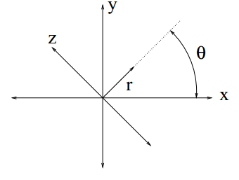
Let us define a new coordinate system $ (r,z) $ where
$ \begin{bmatrix} x \\ y \end{bmatrix} = A_{\theta}\begin{bmatrix} r \\ z \end{bmatrix} $
i.e. vector $ [r,z]' $ is rotated counterclockwise angle $ \theta $ to produce vector $ [x,y]' $
Figure 1 shows the geometric interpretation of the rotation.
- Inverse Transformation
$ \begin{bmatrix} r \\ z \end{bmatrix} = A_{-\theta}\begin{bmatrix} x \\ y \end{bmatrix} $
References
- C. A. Bouman. ECE 637. Class Lecture. Digital Image Processing I. Faculty of Electrical Engineering, Purdue University. Spring 2013.
- E. W. Weisstein, "Rotation Matrix." From MathWorld--A Wolfram Web Resource. http://mathworld.wolfram.com/RotationMatrix.html. May 8th, 2013 [May 21st, 2013]
Questions and comments
If you have any questions, comments, etc. please post them on this page
Back to the "Bouman Lectures on Image Processing" by Maliha Hossain


