(files) |
(image table) |
||
| Line 15: | Line 15: | ||
(To do: insert circuit diagram, input and output signals) <br> | (To do: insert circuit diagram, input and output signals) <br> | ||
| − | + | {| class="wikitable" | |
| − | File:Distortion.jpg| | + | |- |
| − | < | + | ! Circuit !! Output !! |
| + | |- | ||
| + | | [[File:Distortion.jpg|225px|thumb|left]] || [[File:Distortionsignal.gif|225px|thumb|left]] | ||
| + | |} | ||
| + | |||
| + | <br> | ||
2. Analog Delay: This is a difficult circuit to implement. You have to use a delay line IC and it is still hard to have a good signal to noise ratio in this scenario. <br> | 2. Analog Delay: This is a difficult circuit to implement. You have to use a delay line IC and it is still hard to have a good signal to noise ratio in this scenario. <br> | ||
Revision as of 13:42, 23 April 2017
Contents
DSP Audio Effect Applications
by Thomas Stepp
Introduction
If you listen to music, there's a guarantee that you will not hear the exact voice of a singer or the immediate output of an instrument. Instead musicians and vocalists use effects to enhance their sound, craft a unique tone, and as a tool to express themselves.
Some commonly used effects are reverb (to sound like you are playing in a large room), distortion (to achieve a harsher tone and add harmonics), and delay (to create an echo or repeating effect). Many of these were initially created through analog circuits, but it is increasingly more popular to use digital implementations as technology improves and becomes cheaper.
Analog Effects
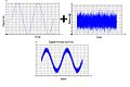
1. Analog Distortion: This is an easy circuit to implement with an amplifier and clipping diodes.
(To do: insert circuit diagram, input and output signals)
| Circuit | Output | |
|---|---|---|
 |
 |
2. Analog Delay: This is a difficult circuit to implement. You have to use a delay line IC and it is still hard to have a good signal to noise ratio in this scenario.
Delay Circuit

Digital World
1. Digital Distortion: A simple implementation for matlab, would be scaling the signal, and then "clipping" the output with a max value:
y[n] = A*x[n]
if y[n] > max, then y[n] = max
if y[n] < -max, then y[n] = -max
Where "A" is a variable scalar greater than one. This could be controlled via a GUI in software or with a potentiometer in hardware. And "max" is the clipping value or max output voltage.
(To do: insert block diagram)
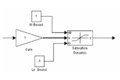
Distortion Block Diagram

2. Digital Delay: Much easier in the digital world compared to the analog world.
y[n] = x[n] + A*x[n - T]
H(z) = 1 + A*z^{-T}
Where "A" is a variable scalar less than or equal to one. It acts as the volume for the delayed signal, so it can match the original signal or be more subtle. And "T" is the delay time. When this value is large enough, you can distinctly here the repeating signal. When this value is smaller, it will have a "chorus" type effect where it sounds like multiple instruments are playing the same notes.
(To do: insert block diagram)
Delay Block Diagram
Conclusion
While audio effects were historically made with analog circuits, digital technology has become cheap and easy to implement. Modeling various audio effects is quite simple and in some cases easier to implement than the hardware counterparts.
References
Stanford PowerPoint with Matlab examples: [1]
Texas Instruments PowerPoint with block diagrams: [2]
Bradley project for real-time audio effects: [3]
McGill book for Digital Audio Effects: [4]
Blog post from dubspot music communinty: [5]