| Line 86: | Line 86: | ||
---- | ---- | ||
| − | == References== | + | == References in IEEE Citation== |
1) C., “YouTube,” YouTube, 04-Nov-2015. [Online]. Available: https://www.youtube.com/watch?v=uihBwtPIBxM. [Accessed: 23-Apr-2017]. | 1) C., “YouTube,” YouTube, 04-Nov-2015. [Online]. Available: https://www.youtube.com/watch?v=uihBwtPIBxM. [Accessed: 23-Apr-2017]. | ||
Revision as of 20:07, 23 April 2017
Contents
[hide]An Implementation of Sobel Edge Detection
by Sean Sodha
Introduction
Edge Detection is when we use matrix math to calculate areas of different intensities of an image. After finding all of the large differences in intensities in the picture, we have covered all of the edges in the picture.Sobel Edge detection is a widely used form of image processing. Along with Canny and Prewitt, Sobel is one of the most popular edge detection algorithms used in today's technology.
The Math Behind the Algorithm
When using Sobel Edge Detection, the image is processed in the X and Y directions separately first, and then combined together to form a new image which represents the sum of the X and Y edges of the image. However, these images can be processed separately as well. That will be covered later in this document.
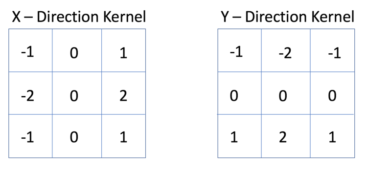
When using a Sobel Edge Detector, it is first best to convert the image from an RGB scale to a Grayscale image. Then from there, we will use what is called kernel convolution. A kernel is a 3 x 3 matrix consisting of differently (or symmetrically) weighted indexes. This will represent the filter that we will be implementing for an edge detection.
When we want to scan across the X direction of an image for example, we will want to use the following X Direction Kernel to scan for large changes in the gradient. Similarly, when we want to scan across the Y direction of an image, we could also use the following Y Direction Kernel to scan for large gradients as well.
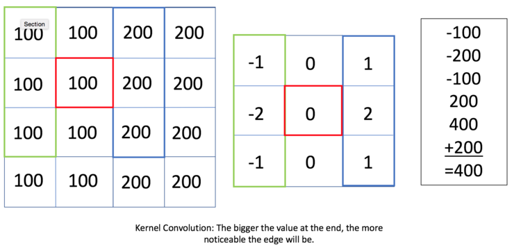
By using Kernel Convolution, we can see in the example image below there is an edge between the column of 100 and 200 values.
This Kernel Convolution is an example of an X Direction Kernel usage. If an image were scanning from left to write, we can see that if the filter was set at (2,2) in the image above, it would have a value of 400 and therefore would have a fairly prominent edge at that point. If a user wanted to exaggerate the edge, then the user would need to change the filter values of -2 and 2 to higher magnitude. Perhaps -5 and 5. This would make the gradient of the edge larger and therefore, more noticeable.
Once the image is processed in the X direction, we can then process the image in the Y direction. Magnitudes of both the X and Y kernels will then be added together to produce a final image showing all edges in the image. This will be discussed in the next section.
Edge Detection Example
Now that we have gone through the mathematics of the edge detection algorithm, it is now time to put it to use on a real image.
Below is the original image that was used in this project:
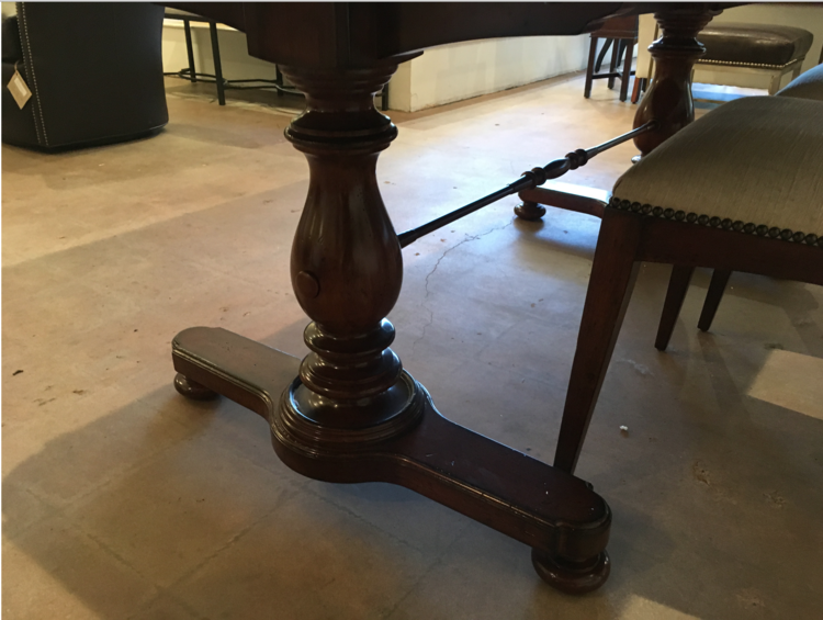
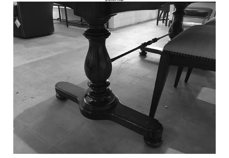
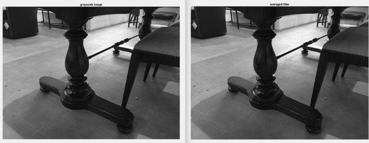
The first step to using Sobel Edge Detection is to convert the image to grayscale. While it is possible to use the algorithm in standard RGB scale, it is easier to implement in a grayscale. Below is the grayscale image.
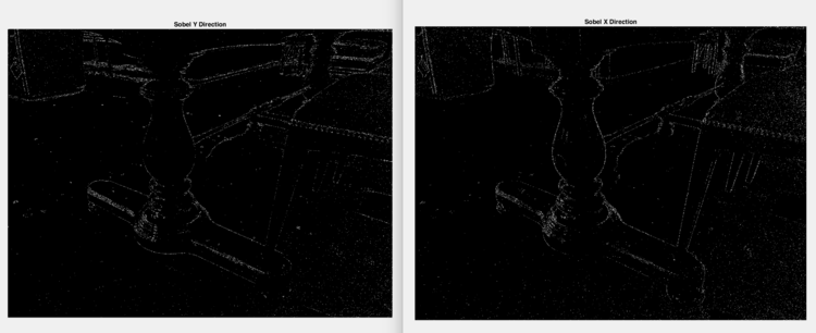
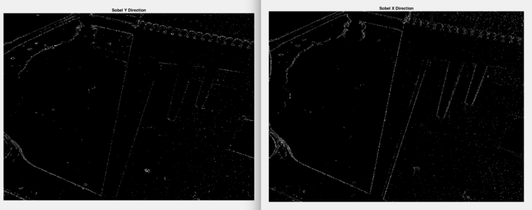
The first step that I want to show is showing the differences between Sobel Edge Detection in the X Direction and in the Y direction individually.
As we can see, the images are fairly similar simply because many of the edges in the image are at an angle. However, we can see that in Sobel Y Direction image, it does not catch a lot of the leg of the chair on the right. This is because when we use the Y direction, we are scanning from top to bottom, and it will only detect edges that are going from left to right. On the other hand, Sobel X Direction will detect the edges of the chair leg because the image will be processed from left to right using a different filter. This will catch the left and right edge of the chair leg. The images below show this distinction.
To emphasize this again, Sobel Y direction did not catch a lot of the chair leg, while Sobel X direction did.
The image below is when the two filters values are added together to create an accurate representation of all of the edges (X and Y Direction) in the image.
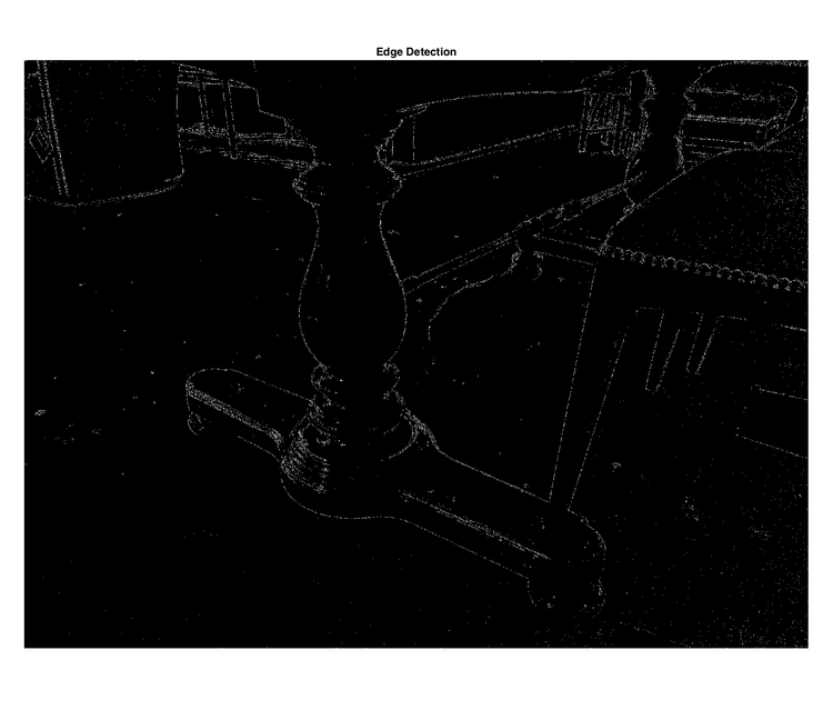
This image above shows all edges in the image.
Common Issues with Sobel Edge Detection
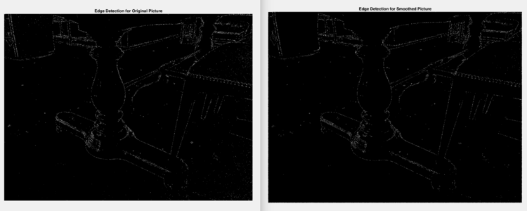
A common issue with Sobel Edge Detection is the fact that there tends to be a lot of noise in the final processed image. As you can see in the image above, there are a lot of white spots or 'snowflakes' that are not meant to be there. A common method on how to reduce the noise in the image is to use an averaging filter to smoothen the image, and then apply the Sobel Edge Detection Algorithm again and compare the differences. Below is an example of an average filter (covered in ECE 438 taught by Professor Boutin):
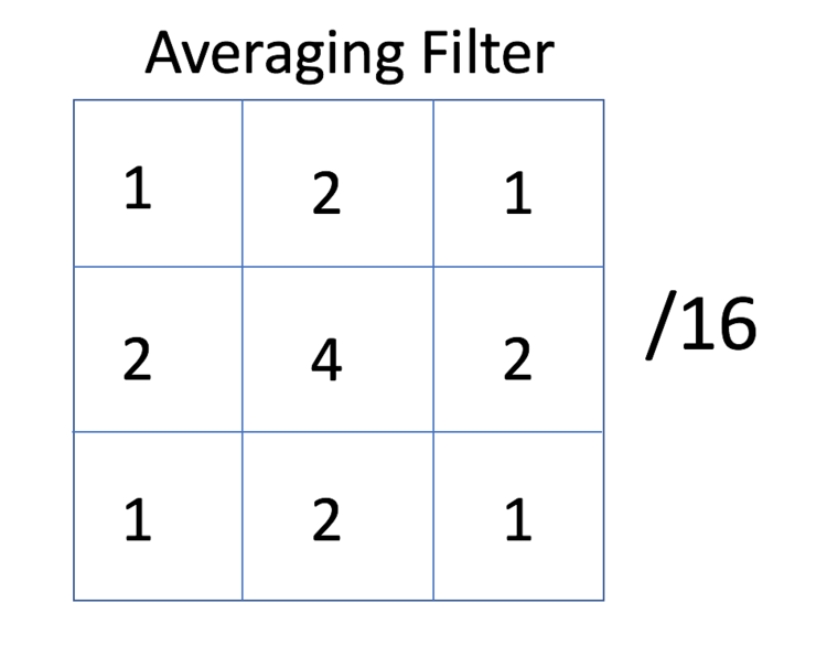
This filter is applied in the same manner as the Sobel Edge Detection matrices.
Below is the grayscale smoothened picture. Not many differences can be noticed at first when compared with the original. However, when applying the Sobel Edge Detection Algorithm, it will make a large difference in the final processed image.
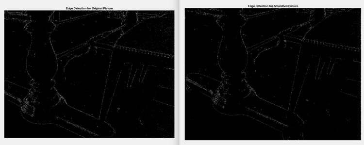
When finally running the Sobel Edge Detection on the averaged filter, the results below show a large difference in the quality of the processed images.
We can see that this works because when we zoom in on different parts of the image (particularly the cushion of the chair) we can see that the noise of the image has been reduced significantly. Below is a zoom in of the cushion. When we average out of the components, we reduce the noise because we eliminate the high frequency components in an image.
References in IEEE Citation
1) C., “YouTube,” YouTube, 04-Nov-2015. [Online]. Available: https://www.youtube.com/watch?v=uihBwtPIBxM. [Accessed: 23-Apr-2017].
2) “Sobel Operator,” www.tutorialspoint.com. [Online]. Available: https://www.tutorialspoint.com/dip/sobel_operator.htm. [Accessed: 23-Apr-2017].
3) “Sobel Edge Detector,” Feature Detectors - Sobel Edge Detector. [Online]. Available: http://homepages.inf.ed.ac.uk/rbf/HIPR2/sobel.htm. [Accessed: 23-Apr-2017].
4) M., “Documentation,” Detecting a Cell Using Image Segmentation - MATLAB & Simulink Example. [Online]. Available: https://www.mathworks.com/help/images/examples/detecting-a-cell-using-image-segmentation.html. [Accessed: 23-Apr-2017].

