Coordinate Rotation and the Radon Transform
A slecture by ECE student Sahil Sanghani
Partly based on the ECE 637 material of Professor Bouman.
Introduction
Medical imaging systems cannot directly create a 3D scan of a person. They can only measure projections through an object with density. A Radon Transform is an integral that allows the calculation of the projections of an object as it is scanned. Since the scanner rotates as it takes data, the projections will have to be calculated at various angles. Thus coordinate rotation is an essential topic for tomographic reconstruction because it allows the calculation of the Radon Transform.
Coordinate Rotation
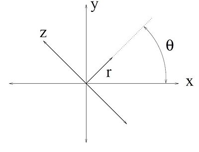
To accommodate the multitude of angles that scans will we taken at, we will introduce a new coordinate system to work with, $ (r,z) $. The relationship between $ (x,y) $ and $ (r,z) $ is shown below. The $ (r,z) $ axes are rotated counterclockwise by $ \theta $ relative to the $ (x,y) $ axes. The geometric meaning of $ (r,z) $ is shown in Figure 1.
$ \begin{bmatrix} x \\ y \end{bmatrix} = \mathbf{A_{\theta}}\begin{bmatrix} r \\ z \end{bmatrix} $
Where $ A_\theta $ is the counterclockwise rotation matrix
$ \mathbf{A_{\theta}}=\begin{bmatrix} \cos(\theta) & -\sin(\theta) \\ \sin(\theta) & \cos(\theta) \end{bmatrix} $
The inverse transformation can be achieved by rotating the opposite direction. Essentially plug in $ -\theta $. This yields
$ \begin{bmatrix} r \\ z \end{bmatrix} = \mathbf{A_{-\theta}}\begin{bmatrix} x \\ y \end{bmatrix} $
Where $ A_{-\theta} $ is
$ \mathbf{A_{-\theta}} = \begin{bmatrix} \cos(\theta) & \sin(\theta) \\ -\sin(\theta) & \cos(\theta) \end{bmatrix} $
Radon Transform
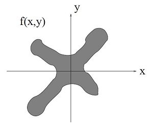
The goal is to find an equation to express a projection $ p_\theta (r) $ of an object with density $ f(x,y) $. We will derive the Radon transform through a parallel projection method. To start let us consider an image with density $ f(x,y) $ shown in Figure 2.
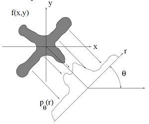
Now we will project the object onto the $ r $ axis along the $ z $ axis as shown in Figure 3. In order to extract $ p_\theta (r) $, a projection integral needs to be taken along z for every $ r $. Every projection line is parallel and perpendicular to the $ r $ axis. This implies that the projection integral is
$ p_{\theta}(r) = \int_{-\infty}^{\infty}f(x,y)dz $
Because we have defined the object in the $ (x,y) $ domain, we can only reference its actual values with $ x $ and $ y $. In order to work with the projection on $ z $, we must map $ (x,y) $ to $ (r,z) $ through the coordinate rotation covered above.
The projection integral for each $ r $ and $ \theta $ is given below. The main coordinates $ (x,y) $ are written in vector form in order to show the substitution of the rotation.
$ \begin{align} p_{\theta}(r) &= \int_{-\infty}^{\infty}f( \begin{bmatrix} x \\ y \end{bmatrix}) dz \\ &= \int_{-\infty}^{\infty}f(\mathbf{A_{\theta}} \begin{bmatrix} r \\ z \end{bmatrix}) dz \\ &= \int_{-\infty}^{\infty} f( \begin{bmatrix} \cos(\theta) & -\sin(\theta) \\ \sin(\theta) & \cos(\theta) \end{bmatrix} \begin{bmatrix} r \\ z \end{bmatrix}) dz \\ &= \int_{-\infty}^{\infty} f(r\cos(\theta)-z\sin(\theta),r\sin(\theta)+z\cos(\theta))dz \end{align} $
This is the definition of the Radon transform. Restated:
$ p_{\theta}(r) = \int_{-\infty}^{\infty} f(r\cos(\theta)-z\sin(\theta),r\sin(\theta)+z\cos(\theta))dz $
Note: looking back at Figure 3, you can see that the projection corresponding to $ r = 0 $ goes through the point $ (x,y) = (0,0) $.
References:
[1] C. A. Bouman. ECE 637. Class Lecture. Digital Image Processing I. Faculty of Electrical Engineering, Purdue University. Spring 2013.
Questions and Comments
Please post your questions and comments on the discussion page.


