| Line 66: | Line 66: | ||
Before implementing my code on the ATTiny, I wanted to do some verification and evaluate performance. Fortunately, Octave has a [C/C++ api](https://www.gnu.org/software/octave/doc/v4.0.1/Getting-Started-with-Oct_002dFiles.html) which allowed me to test my code with the same bit-precision as I would have on the microcontroller. Shown below is my first shot at modulating and demodulating a signal at 600 bits/s. | Before implementing my code on the ATTiny, I wanted to do some verification and evaluate performance. Fortunately, Octave has a [C/C++ api](https://www.gnu.org/software/octave/doc/v4.0.1/Getting-Started-with-Oct_002dFiles.html) which allowed me to test my code with the same bit-precision as I would have on the microcontroller. Shown below is my first shot at modulating and demodulating a signal at 600 bits/s. | ||
| − | [[File:Fsk_modulation.png|center|800px|Modulated signal]] | + | [[File:Fsk_modulation.png|thumb|center|800px|Modulated signal]] |
| − | [[File:demod.png|center|800px|Demodulation]] | + | [[File:demod.png|thumb|center|800px|Demodulation]] |
| − | [[File:demod_lpf.png|center|800px|Demodulation with lowpass applied]] | + | [[File:demod_lpf.png|thumb|center|800px|Demodulation with lowpass applied]] |
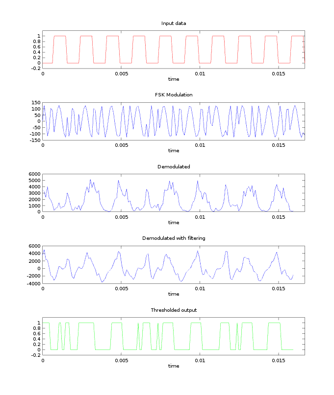
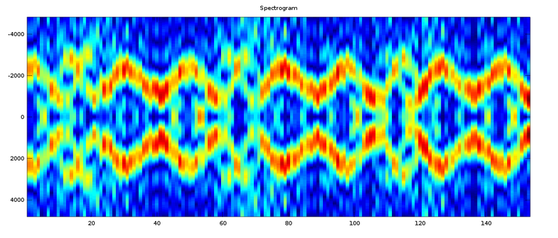
Initially, I generated my test signals incoherently, meaning that the phase resets each time the signal transitions from a mark to a space and vice versa. This creates discontinuities and adds noise to the spectrum in the transition regions. From the results below, it was clear that my implementation really needed to be coherent. | Initially, I generated my test signals incoherently, meaning that the phase resets each time the signal transitions from a mark to a space and vice versa. This creates discontinuities and adds noise to the spectrum in the transition regions. From the results below, it was clear that my implementation really needed to be coherent. | ||
| − | [[File:modulation_incoherent.png|center|800px|Incoherent test signal. Notice jumps in the generated signal]] | + | [[File:modulation_incoherent.png|thumb|center|800px|Incoherent test signal. Notice jumps in the generated signal]] |
| − | [[File:spectrogram_incoherent.png|center|800px|Spectrogram view of incoherent test signal. There is noticeable `fuziness` in the transition regions.]] | + | [[File:spectrogram_incoherent.png|thumb|center|800px|Spectrogram view of incoherent test signal. There is noticeable `fuziness` in the transition regions.]] |
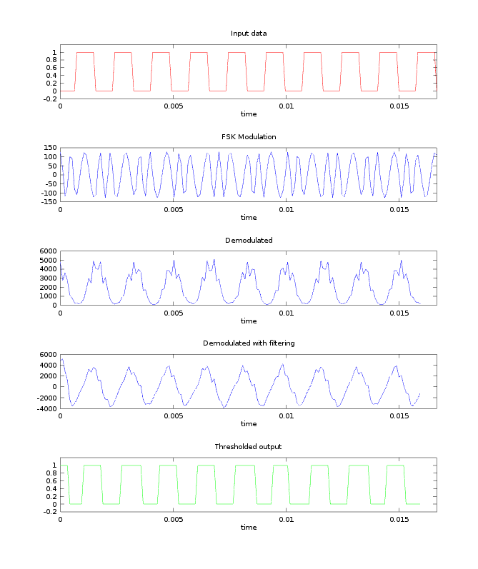
| − | [[File:modulation_coherent.png|center|800px|Coherent test signal. No more discontinuities.]] | + | [[File:modulation_coherent.png|thumb|center|800px|Coherent test signal. No more discontinuities.]] |
| − | [[File:spectrogram_incoherent.png|center|800px|Spectrogram view of coherent test signal. cleaner transitions between frequencies.]] | + | [[File:spectrogram_incoherent.png|thumb|center|800px|Spectrogram view of coherent test signal. cleaner transitions between frequencies.]] |
Once the filter was working in simulation, I designed some PCBs, moved it to the ATTiny85 and began physical testing. | Once the filter was working in simulation, I designed some PCBs, moved it to the ATTiny85 and began physical testing. | ||
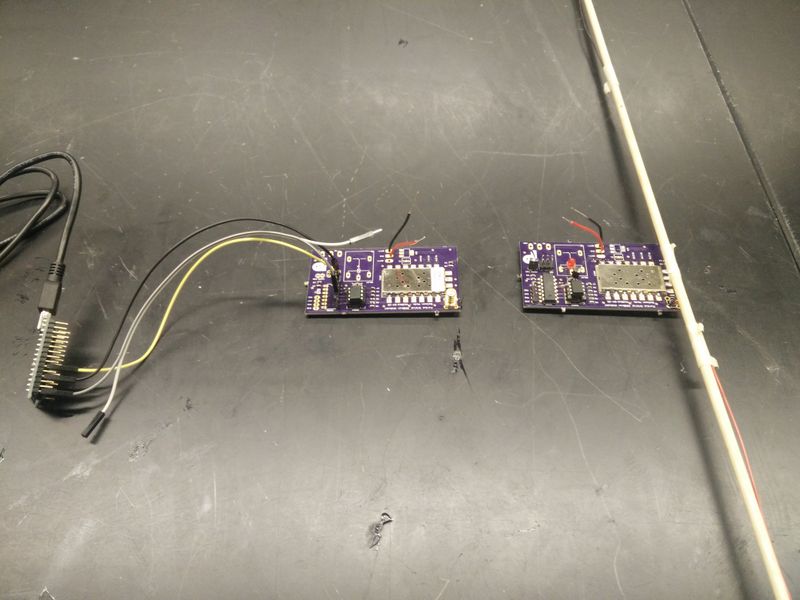
| − | [[File:modem_testing.jpg|center|800px|Direct modem-to-modem comms testing]] | + | [[File:modem_testing.jpg|thumb|center|800px|Direct modem-to-modem comms testing]] |
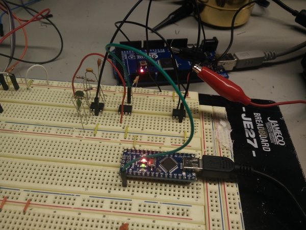
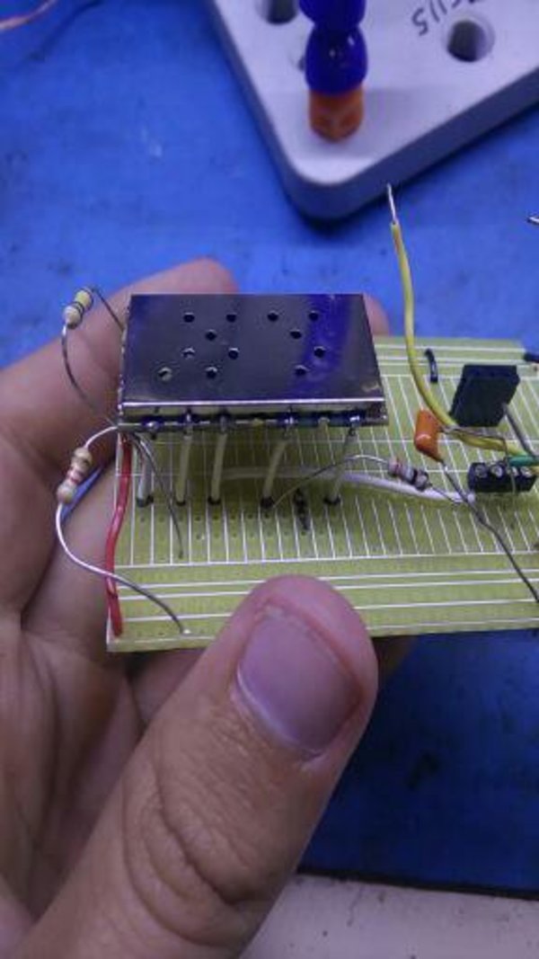
| − | [[File:prototype.jpg|center|800px|Radio breadboarding and testing]] | + | [[File:prototype.jpg|thumb|center|800px|Radio breadboarding and testing]] |
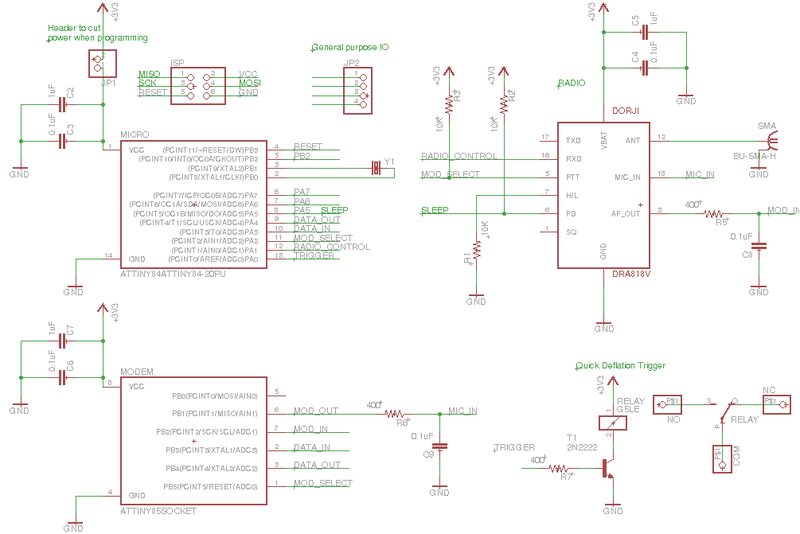
| − | [[File:sch.png|center|800px|Schematic]] | + | [[File:sch.png|thumb|center|800px|Schematic]] |
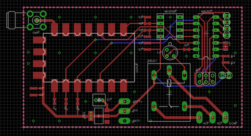
| − | [[File:brd.png|center|800px|Board]] | + | [[File:brd.png|thumb|center|800px|Board]] |
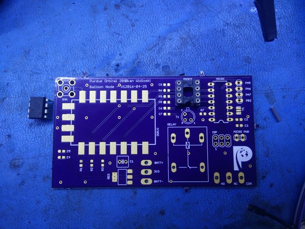
| − | [[File:pcb.jpg|center|800px|PCB Received]] | + | [[File:pcb.jpg|thumb|center|800px|PCB Received]] |
| − | [[File:pair.jpg|center|800px|Finished pair]] | + | [[File:pair.jpg|thumb|center|800px|Finished pair]] |
Revision as of 07:38, 26 November 2016
This is a prototype for a high altitude balloon project I worked on with the Purdue Orbital rocketry team. I designed this board to test the range and power draw of our comms system and threw on a relay and microcontroller so that it can be used for triggering things on a real flight.
Parts list
   * Baofeng DRA818V
   * Attiny 84
   * Attiny 85
   * Relay
   * Regulator
One of the FAA requirements is that balloons over a certain weight have four cutdown systems (two on the balloon envelope and two on the payload tether) and that these systems must be independent, meaning they are electrically disconnected from each other and have separate batteries. Many amateurs balloonists overlook this rule, but due to our close work with the FAA it is important that we follow the regulations.
To save on cost, I avoided the higher end radio specific devices on the market and stuck to hobby-tier components. First was the Baofeng DRA818V. This is cheap Chinese VHF transceiver that costs less than $20 on Amazon and has a decent amount of power. Some users claim that these devices bleed onto other channels and should have a lowpass filter on the output (mine is inline with the coax). There is also a UHF band available, but I chose VHF for potential future compatibility with the [APRS](https://en.wikipedia.org/wiki/Automatic_Packet_Reporting_System) system. APRS will be an essential part of the system, because most radios in this power level (0.5 - 1W transmission) can only achieve a few dozen miles tops transmitting from ground to balloon. The incorporation of APRS will greatly extend this range by taking advantage of amateur repeating stations called `digipeaters`.
Since this radio module is for handheld units that transmit audio, I needed some sort of modem for converting data to an analog format and vice-versa. One of the methods of modulation I investigated was DTMF, which is used commonly in amateur radio and is built in to many consumer units. However, DTMF modems tend to be rather large pin-wise and aren't compatible with most digipeaters, so I decided to build one from scratch using my favorite microcontroller, the ATTiny85. For starters, I need to modulate and demodulate incoming data (known as `symbols` in communications) so they can be transmitted over the air. In this case, most digipeaters use a standard known as `Bell-202` (also known as AFSK-1200), which is a simple modulation scheme where a logic 1 (mark) is represented by a 1200 Hz tone and a logic 0 (space) is represented by a 2200 Hz tone. I accomplished this by calculating an 8-point DTFT at 1200 Hz and 2200 Hz at a sample rate of 9600 Hz (determined through testing). I didn't use the FFT here because I'm only interested in the spectral power at two points.
I took some inspiration from this blogpost where somebody used an ATTiny as a software modulator/demodulator at 1200baud. It was written in assembly for the ATTiny10, which has incompatible hardware with the ATTiny85 and is not portable to other platforms.
Once I generated my DTFT coefficients, I used the Q number format, which is a method of handling signed fractional numbers within fixed point datatypes. I wrote a bit of code to do the conversion.
Calculating coefficients
     #!/bin/octave
     ## Evan Widloski - 2016-10-15
     ## calculate DTFT coefficients and express as binary fractions
     ## ----- Convert decimal numbers to n bit signed binary fractions -----
     function out = dec2binfrac(x,n)
       ## round input array to nearest 1/(2^n)
       x = round(x * 2^n)/(2^n);
       k = [1:n-1];
       if (x < 0)
         x = 1+x;
         out = -2^(n-1);
       else
         out = 0;
       endif
       twos_complement = mod(abs(x),.5.^(k-1)) >= .5.^k;
       bin_values = 2.^[n-2:-1:0];
       out += sum(bin_values .* twos_complement);
     endfunction
     ## ----- Create coefficients for implementation in C -----
     N = 8
     ## generate DFT coefficients
     Xd1 = e.^(-i*2*pi*(1200/9600)*[0:N-1]);
     Xd2 = e.^(-i*2*pi*(2200/9600)*[0:N-1]);
     ## scale down coefficients by 1 bit, since `1` can't be expressed as binary fraction
     ## e.g. scale 1 to 127/128
     Xd1 = Xd1*((2^(N-1) - 1)/2^(N-1));
     Xd2 = Xd2*((2^(N-1) - 1)/2^(N-1));
     ## express coefficients as signed N-bit binary fractions (Q7)
     arrayfun(@(x) dec2binfrac(x,N),real(Xd1))
     arrayfun(@(x) dec2binfrac(x,N),imag(Xd1))
     arrayfun(@(x) dec2binfrac(x,N),real(Xd2))
     arrayfun(@(x) dec2binfrac(x,N),imag(Xd2))
This yielded 4 arrays which would calculate the DFT at 1200 and 2200 Hz with a 9600 Hz sample rate.
Simulation
Before implementing my code on the ATTiny, I wanted to do some verification and evaluate performance. Fortunately, Octave has a [C/C++ api](https://www.gnu.org/software/octave/doc/v4.0.1/Getting-Started-with-Oct_002dFiles.html) which allowed me to test my code with the same bit-precision as I would have on the microcontroller. Shown below is my first shot at modulating and demodulating a signal at 600 bits/s.
Initially, I generated my test signals incoherently, meaning that the phase resets each time the signal transitions from a mark to a space and vice versa. This creates discontinuities and adds noise to the spectrum in the transition regions. From the results below, it was clear that my implementation really needed to be coherent.
Once the filter was working in simulation, I designed some PCBs, moved it to the ATTiny85 and began physical testing.


