| Line 1: | Line 1: | ||
| + | == Introduction == | ||
| + | |||
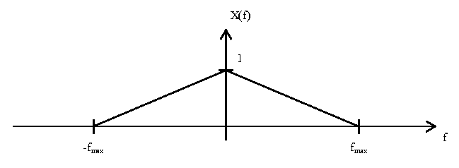
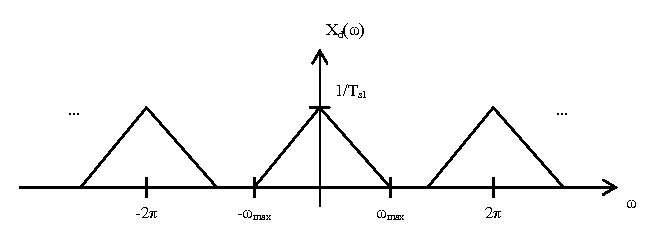
| + | == A Representative DT Signal == | ||
| + | |||
[[Image:X_f_plot.png]] | [[Image:X_f_plot.png]] | ||
[[Image:Xd_w_plot.png]] | [[Image:Xd_w_plot.png]] | ||
| + | |||
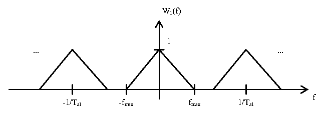
| + | == Without Upsampling == | ||
[[Image:Dac_diag.png]] | [[Image:Dac_diag.png]] | ||
[[Image:W1_f_plot.png]] | [[Image:W1_f_plot.png]] | ||
| + | |||
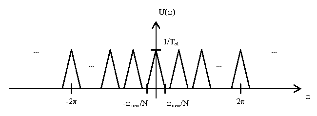
| + | == With Upsampling == | ||
[[Image:Upsampling_diag.png]] | [[Image:Upsampling_diag.png]] | ||
| Line 9: | Line 17: | ||
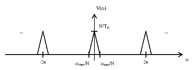
[[Image:V_w_plot.png]] | [[Image:V_w_plot.png]] | ||
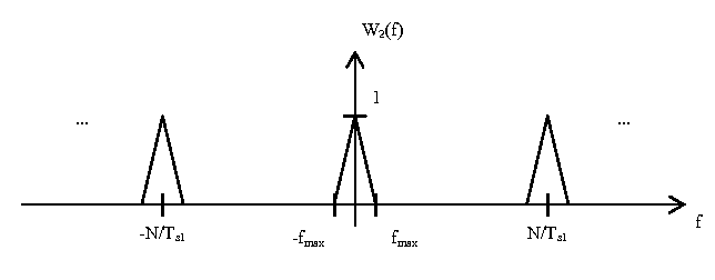
[[Image:W2_f_plot.png]] | [[Image:W2_f_plot.png]] | ||
| + | |||
| + | == How Analog Filter Design is Affected == | ||

