Determining Orientation from Accelerometer (alec green)
OUTLINE
. introduction
. continuous equations (..to be completed..)
. discretization (..to be completed..)
. references
Introduction
An accelerometer is useful for measuring orientation relative to Earth's surface ground ('static acceleration' due to gravitational force) or accelerating motion throughout space ('dynamic acceleration' due to non-gravitational force such as a car speeding up or a human shaking an accelerometer-clad device). However, note that accelerometers are implicity restricted to measuring acceleration, and cannot measure velocity. For example, constant nonzero velocity will produce same measurement as zero velocity.
It's important to first determine if an accelerometer is appropriate for your application. If you're not sure, you may consider other orientation/position sensing devices such as: gyroscope (angular velocity), magnetic compass (2D direction of maximum local magnetic field), magnetometer (magnitude and 3D direction of local magnetic field), GPS (rough 3D position).
In order to achieve higher-level measurements such as 'dead reckoning' (calculation of position and orientation in 3D space), you will need to combine sensor readings. For example, an accelerometer, gyroscope, and magnetometer are commonly packaged together as an 'intertial measurement unit' (or IMU) to be used by 'quadcopter' hobbyists. This 'sensor fusion' also allows for sensors to recalibrate each other such that measurement 'drift' of certain sensors (esp. gyroscope) is minimized. This inter-recalibration can further benefit from probabilistic noise-reducing filters such as the Bayesian or Kalman filter.
The following video may give you a better idea of what an accelerometer can be used for. Extensive description provided at YouTube page (access by clicking on YouTube logo in lower right-hand side of video).
Continuous Equations
It's instructive to read through pages 3-4 of [2] in order to understand how an accelerometer works on a physical level, but not necessary to interpret the analog or digital signals generated from the sensor.
Discretization
Because an HCS12 microcontroller works with fixed-point integers, computing the required arctangent (and sqrt equations is non-trivial. The atan function you might normally invoke from the <math.h> library requires floating point numbers. An example implementation can be seen here [4].
However, because this application dealt with an embedded microprocessor, I considered two atan implementations from [4]:
- 'closed form' (finite number of terms) approximation, whose range is inherently bounded to [-45 degrees,+45 degrees].
$ arctan(x) \approx \frac{x}{1 + .28125x^{2}} , -1 \leq x \leq 1 $
- lookup table (LUT) (w/ or w/o interpolation), in which the arctan argument is used as an index to the LUT.
The closed form approximation may seem simple to implement requires about as much processing time (2 sqrt calls) as the more accurate LUT implementation (1 sqrt call + 2 table lookups), I opted for the LUT. Also, you'll notice the fractional number '.28125' in the denominator of closed form approximation, which would require non-natural placement of the fixed-point decimal in order to calculate (additional cycles).
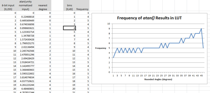
Because the neither accuracy nor range of sensitivity was critical for my application, I implemented a relatively small 256-value LUT in which each arctan argument was multiplied by 255. This means that arctan_LUT[255] = 45 degrees, or in other words, all arctan arguments are normalized and bounded to '1'. However, the LUT could easily be extended up to 90 degrees in both directions by using a larger table or a smaller scaling constant.
To deal with negative arguments, I utilized the property that: $ arctan(-x) = -arctan(x) $ Explicitly, I set a 'negative flag' if the arctan to be calculated had a negative argument, and fed in the absolute value of the argument to the lookup table, finally appending a 'negative sign' to the table value if appropriate. This effectively doubles the LUT size, and also saves me the hassle of dealing with negative numbers (two's complement). Little tricks like this are useful when dealing with a fixed-point microprocessor, even though they would be trivial and unnecessary for a modern PC's memory and processing resources.
Details of an LUT implementation (w/o interpolation) can be seen in the following graphs. You can see that upper bound of angle calculation is .5 degrees, which is more than acceptable for my application.
A finished implementation (with atan LUT), displaying analog axis outputs and calculated orientation angles (roll, pitch) can be seen here. As before, an explanation of the video can be found on the original Youtube page.
References
[1] Freescale Semiconductor, "±1.5g, ±6g Three Axis Low-g Micromachined Accelerometer" Freescale Datasheet. <http://www.sparkfun.com/datasheets/Components/General/MMA7361L.pdf>
[2] L. Salhuana, "Tilt Sensing Using Linear Accelerometers," Freescale Application Note. <http://www.freescale.com/files/sensors/doc/app_note/AN3461.pdf>
[3] "atan.c," Apple Open Source. <http://opensource.apple.com/source/Libm/Libm-315/Source/Intel/atan.c>
[4] A. Ukil et al., "Fast Computation of arctangent Functions for Embedded Applications: A Comparative Analysis," IEEE ISIE 2011. <http://ieeexplore.ieee.org/xpls/abs_all.jsp?arnumber=5984330>
[5] N. Jones, "A tutorial on lookup tables in C", EmbeddedGurus.com. <http://embeddedgurus.com/stack-overflow/2010/01/a-tutorial-on-lookup-tables-in-c/>
[6] "Fast square root in C," IAR Application Note. <http://netstorage.iar.com/SuppDB/Public/SUPPORT/000419/AN-G-002.pdf>


