Answers and Discussions for
Problem 1, part a
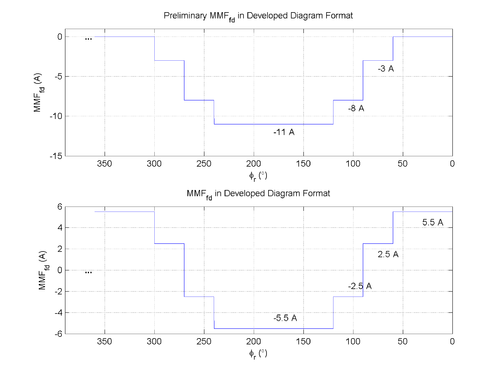
A developed diagram approach is used, "unrolling" the machine such that increasing $ \phi $ (counterclockwise as drawn) is to the left.
Magnetomotive force (MMF) for a machine with concentrated windings may be found as $ \mathcal{F} = \int_{\phi = 0}^{360^\circ} N(\phi) i \, d\phi $. The current is $ i_{fd} = 1 \, \textrm{A} $.
It is given that $ N_{fd1} = \mp 5 $ at an inferred position of $ \phi_r = 90^\circ $ and $ \phi_r = 270^\circ $, $ N_{fd2} = \mp 3 $ at an inferred position of $ \phi_r = 60^\circ $ and $ \phi_r = 240^\circ $, and $ N_{fd3} = \mp 3 $ at an inferred position of $ \phi_r = 120^\circ $ and $ \phi_r = 300^\circ $.
Because $ \oiint_S \vec{B} \cdot d\vec{S} = 0 $, including on the interior surface of the stator and ends of the machine, the average value in the developed diagram of $ B(\phi_r) $ must be 0. The average value of MMF must also be 0 because the airgap is constant, meaning that $ \mathcal{F}(\phi_r) $ and $ B(\phi_r) $ are proportional to each other in the airgap from $ B(\phi_r) = \frac{\mu_0 \mathcal{F}(\phi_r)}{g} $. Thus, the offset of -5.5 A is removed.


