Contents
[hide]Digital Filters: An Introduction
Objectives:
Digital filters are used for two main purposes below. A big advantage for digital filters over analog ones is that digital filters can satisfy criteria for filters far better than analog ones. This slecture hopes to share characteristics important to digital filter use and design in addition to how concepts learned in ECE 438 apply to actual filter design.
1. Separation of signals that have been combined
2. Restoration of signals that have been distorted in some way
Basic Characteristics
When designing filters, it is important to understand where the desired/important information is contained in the signal of interest. In a time-domain important signal, desired information is contained in the amplitude changes when an event occurs, for example, intensity of sunlight on a forest floor over time. Meanwhile in the frequency-domain, one is primarily concerned with the information contained in a signal's component sinusoids.
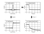
The step response and the frequency response of a filter or system of filters provides a way to understand how a filter will affect our signal of interest. The step response is the integrated impulse response and will show how the filter will affect the signal in the time-domain. On the other hand, the frequency response will show how the info will be changed in the frequency domain.
Some additional points to consider in digital filters for time-domain applications are (1) rise-time, (2) overshoot, and (3) phase changes and for frequency-domain applications are (1) passband ripple, (2) stopband attenuation, and (3) roll-off speed.
Finite Impulse Response and Infinite Impulse Response
Finite impulse response filters (FIR) convolve the impulse response of a system with the signal(s) of interest. The impulse response finite and also referred to as a filter kernel. Thanks to their limited duration, they can be convolved with signals of interest for amazing performance but will be orders of magnitude slower than IIR filters.
Examples of FIR filers are the Moving Average Filter, Hamming, Blackman, and the Windowed Sinc.
The amazing performance of FIR filters can be explained by zero padding the impulse response. Zero padding the impulse response refers to the addition of an arbitrary (even really really large numbers!) number of zeros to the end of the impulse response. Regardless of the size of the zero padding, the convolution of the impulse and the signal will still be the same! The convolution process is a multiply and sum of all the points between the input signal and the system and the zeros will simply sum to 0.
Since the Fourier Transform of the impulse response is the frequency response of the filter, when we take the Fourier Transform of the zero padded impulse response, we end up with better resolution (more points to transform)! In the case with infinitely many zeros, the gap between points in the frequency response from 0 to 1/2 * fs become infinitesimally small. We approach a continuous frequency response!
Infinite impulse response filters (IIR) rely on both system inputs and system outputs to produce new outputs. Their reliance on previous outputs means that they are implemented in a recursive fashion and are also referred to as recursive filters. Their implementation is much much faster than that of FIR filters. The convolution process used in FIR involves a large number of additions and multiplications while the recursive process of IIR filters allows us to simply refer to previous outputs with a slight modification to arrive at a new output.
Examples of IIR filters are the Chebyshev, Butterworth, and Bessel.
Additional information for both FIR and IIR filters can be found on previous slectures concerning the Z-Transform.
Low Pass Filters
The above FIR and IIR filters can be made into filters of all shapes and sizes, but a fundamental is the low pass filter. The low pass filter allows low frequencies to pass through but filters out high frequencies. Its beauty is that it can be manipulated through addition, multiplication, and convolution to turn into high pass filters, band pass filters, and, in fact, all other filter types!
(Note: the filter must be symmetric for the process below to work)
Examples:
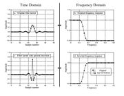
1. Spectral Inversion for a high pass filter
- Multiply the impulse response of the low pass by -1.
- Then add a delta function (an all pass filter) at the center of symmetry.
Changing the sign of the impulse response of a Low Pass Filter by itself will not change it into a high pass filter. However, adding the delta function at the center of symmetry will result in an all pass filter subtracted by a low pass filter or a high pass filter.
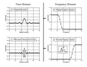
2. Spectral Reversal for a high pass filter
- Flip the sign of every other sample, which will flip the frequency domain left for right.
Changing the sign of every other sample will actually shift the frequency domain by /pi units. The result is that the negative frequencies from -1/2*fs to 0 will get shifted to 0 to 1/2*fs.
3. Band Pass and Band Reject
Band Pass - Add the low and high pass filters together. Band Reject - Convolve the low and high pass filters.
Sources
[1] The Scientist and Engineer's Guide to Digital Signals Processing, Chapter 14. http://www.analog.com/media/en/technical-documentation/dsp-book/dsp_book_Ch14.pdf.


