Contents
[hide]Introduction
With microprocessors becoming ever increasingly faster, smaller, and cheaper, it is preferable to use digital signal processing as a way to compensate for distortions caused by analog circuitry. One area that this can be applied is in signal reconstruction, where a low pass analog filter is used on the output of a digital-to-analog converter to attenuate unwanted frequency components above the Nyquist frequency.
The problem with analog low pass filters is that higher the order, the more resistors, capacitors, and op-amps are required in its construction. More circuit components means more circuit board space, which is a precious commodity with today's hand-held devices.
Here, it will be explained how up-sampling can be used to relax requirements on analog low pass filter design while decreasing signal distortion.
A Representative DT Signal
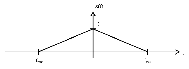
For this discussion, a representative signal $ x(t) $ will be used to demonstrate the process of signal reconstruction. We will look at the signal in the frequency domain, as shown in the plot below:
As seen in the plot, the signal $ X(f) $ has a triangular shape and is band-limited by $ f_{max} $. By the Nyquist-Shannon Sampling Theorem, the sampling frequency $ f_{s1} $ must be greater than $ 2f_{max} $. For this discussion, assume $ f_{s1} $ is just slightly greater than $ 2f_{max} $.
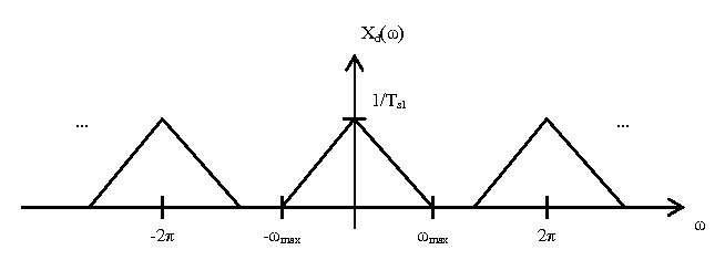
Now, we are going to sample $ x(t) $ with an impulse train with period $ T_{s1} = 1/f_{s1} $ and convert to a discrete time signal. This has the affect of scaling the magnitude axis of $ X(f) $ by $ 1/T_{s1} $ and the frequency axis by $ 2\pi T_{s1} $, and then repeating the result every $ \omega = 2\pi $. This yields the following plot $ X_d(\omega) $:
Without Up-sampling
First, consider the process of signal reconstruction without up-sampling. The following diagram shows the process:
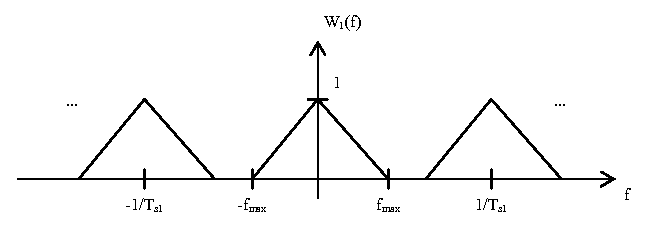
The first block is a digital-to-analog converter. This converts the discrete time signal to a continuous time signal. This has the effect of scaling the magnitude axis by $ T_{s1} $ and the omega axis by $ \frac{1}{2\pi T_{s1}} $. This yields the following plot $ W_1(f) $:
The next step is to use an analog low pass filter to remove all frequency components above $ \frac{1}{2T_{s1}} $. The important note to take from $ W_1(f) $ is that the frequency gap for which the analog filter has to transition from low attenuation to high attenuation is $ \frac{1}{T_{s1}} - 2f_{max} $.
With Up-sampling
Now, consider the process of signal reconstruction with up-sampling. The following diagram shows the process:
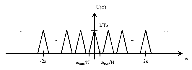
The first block is the up-sample by $ N $ operator, where $ N\in \mathbb{N} $. This inserts $ N-1 $ zeros between each point in the time domain. In the DTFT domain, this has the effect of scaling the omega axis by $ 1/N $. This yields the following plot $ U(\omega) $.
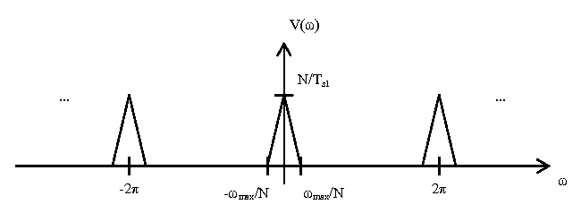
The next block is an interpolator, which is a discrete-time low pass filter with gain $ N $ and cutoff frequency $ f_c = \frac{\pi}{N} $. This removes all extra DTFT components not centered around $ 2\pi k, \forall k \in \mathbb{Z} $, and scales the magnitude axis by N. This yields the following plot $ V(\omega) $:
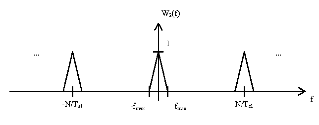
Next is the digital-to-analog converter. This is the same process as in the previous section, but now the sampling period is $ T_{s2} = \frac{T_{s1}}{N} $ due to the up-sampler. This yields the following plot $ W_2(f) $:
The final step is to use an analog low pass filter to remove all frequency components above $ \frac{1}{2T_{s2}} $. The important note to take from $ W_2(f) $ is that the frequency gap for which the analog filter has to transition from low attenuation to high attenuation is now $ \frac{N}{T_{s1}} - 2f_{max} $.
How Analog Filter Design is Affected
By comparing the results of the previous two systems (with and without the upsampler), it can be seen that adding an up-sampler to the system increases the frequency gap for the analog low pass filter from $ \frac{1}{T_{s1}} - 2f_{max} $ to $ \frac{N}{T_{s1}} - 2f_{max} $. A larger N results in a wider frequency gap, which means that the analog filter can be of a smaller order and still maintain minimal distortion. The advantage of this method is that up-sampling and interpolation can be done in an existing microcontroller via software, which requires virtually no extra circuit board space. This would prove especially beneficial in devices such as high quality hand-held mp3/CD players.

